
Emily Chen
Mentor: Professor Andre Schleife
National Center for Super Computing Applications SPIN project
Univerity of Illinois at Urbana Champaign
Introduction
Please note that some of the images on this page may not load if using Mozilla Firefox. For best results, please use Google Chrome to view this page.
The goal of this project has been to observe material’s optical properties through raytracing and to automate the 3D modeling and rendering process to make the program more user-friendly and accessible. We would love to see this program assist researchers in materials design by allowing them to alter the spectral properties and optical absorption until the desired optical properties of the materials is achieved. Because the engine we use is a physically based rendering engine, the resulting images produced will reflect the ideal material’s optical properties.
We have been utilizing and experimenting with Blender as a 3D modeling engine, and LuxRender as the physically based rendering engine. In order to automate the process, we have currently created python scripts which can create different scenes with different objects to apply the material data to. We have been running all of the scripts on the Campus Clusters at the University of Illinois at Urbana-Champaign, allowing most of the runs to render for approximately four hours.
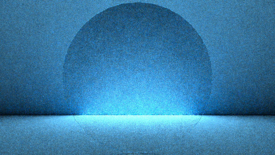
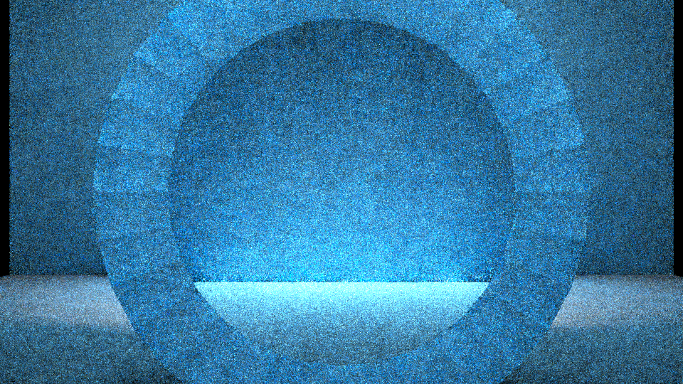
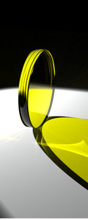
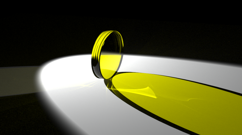
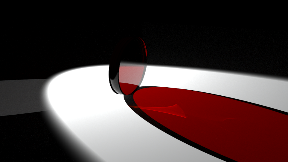
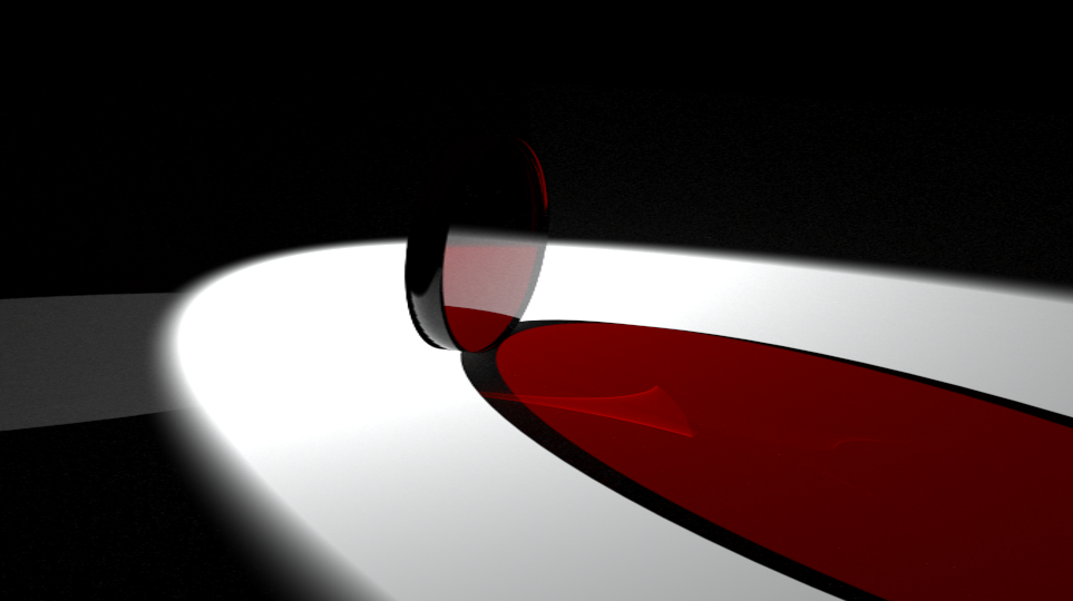
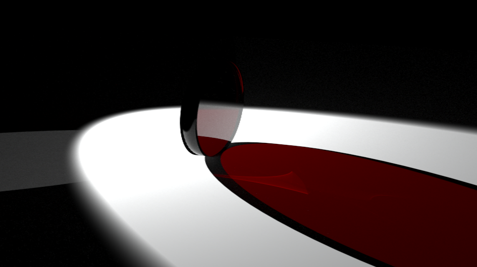
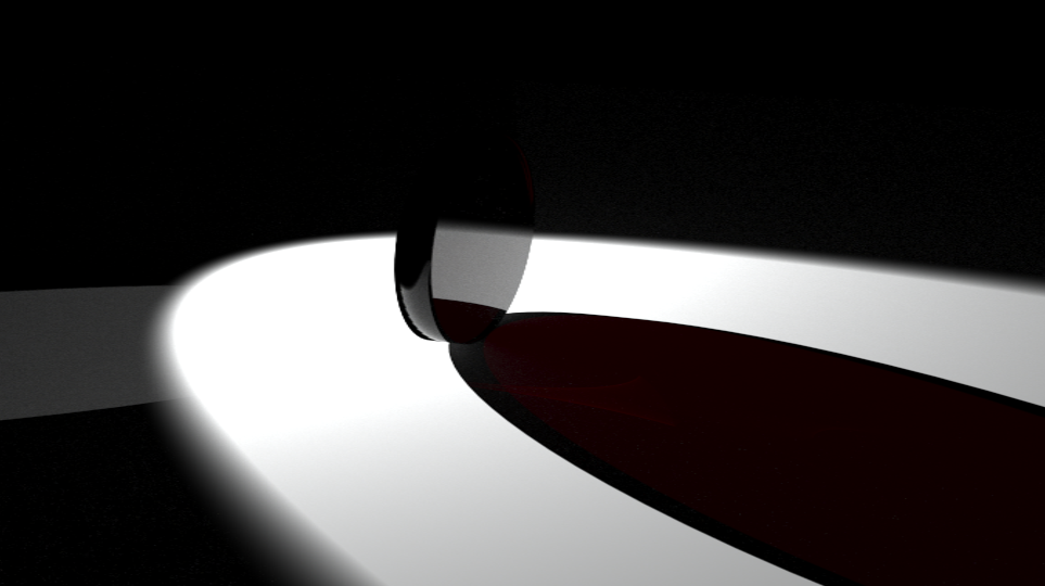
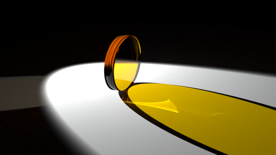
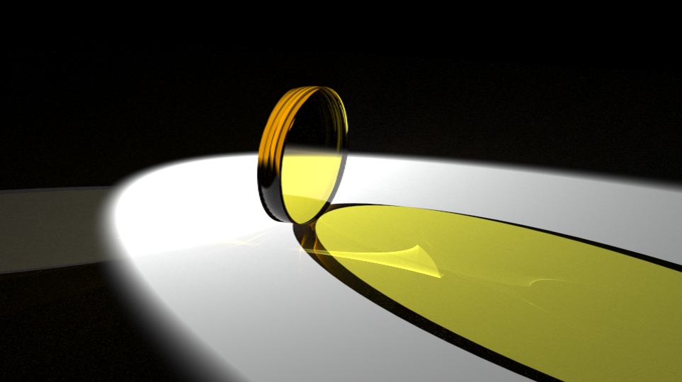
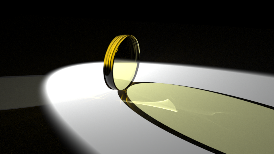
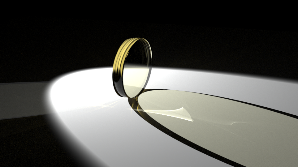
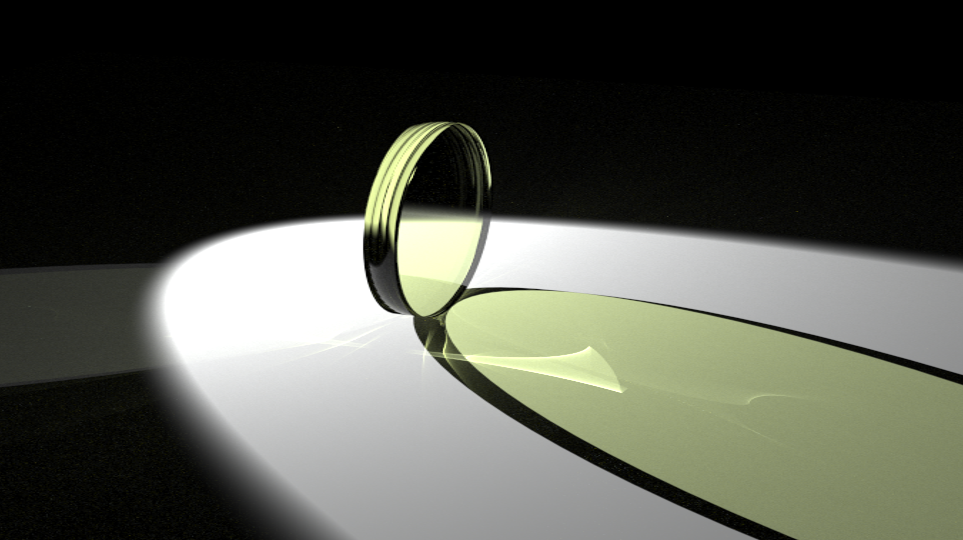
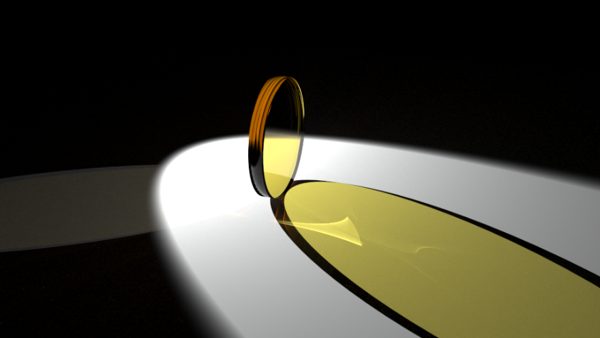
We ran several sweeps to see how the materials’ optical properties would change as different traits of the materials are changed. The first run was varying the physical lengths of the materials to see how length would be rendered though Blender and LuxRender. This, however, seemed to make no change in the light transmission through the material, even though we expected that as the length would increase, the light transmission would decrease. We placed the light source directly behind the material, while changing the length in metric units in Blender. However, the results remained constant, as can be seen below in some of the images from the runs. The object used in the runs was a polygon shaped lens that we increased the thickness of throughout the runs. The thickness of the materials were 1 cm, 1 m, 5 m and 10 m respectively. The background planes were to provide a backdrop for the runs, and the light source was placed directly behind the lens.
We also created Python scripts that can automatically generate absorption spectrum .dat files. This allows researchers to create the input .dat files easily to render a large range of values for their specific sweep. We have been using the following equations to generate the .dat files, and the resulting .dat files give the wavelength (nm) and the absorption spectrum at that specific wavelength (1/cm):


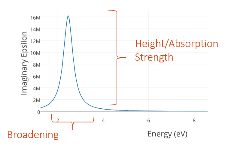
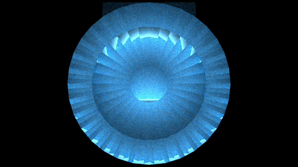
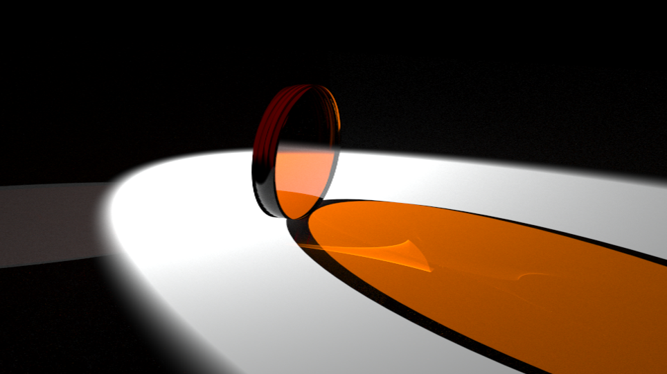
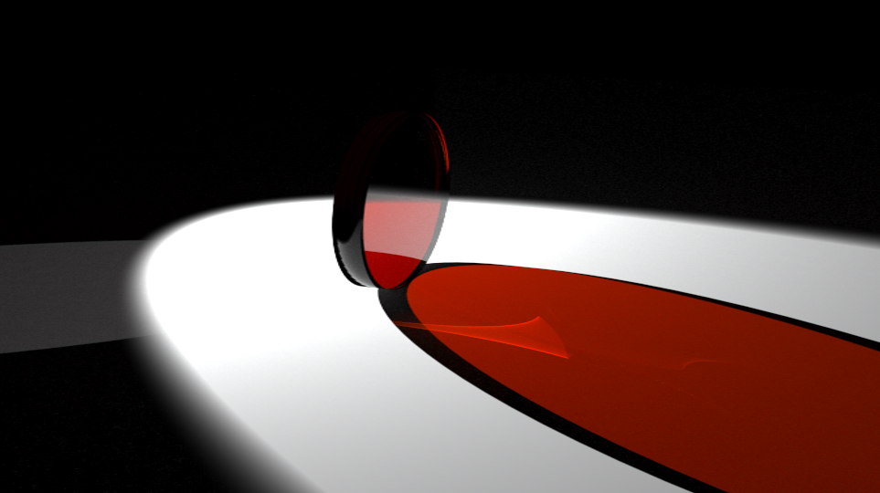
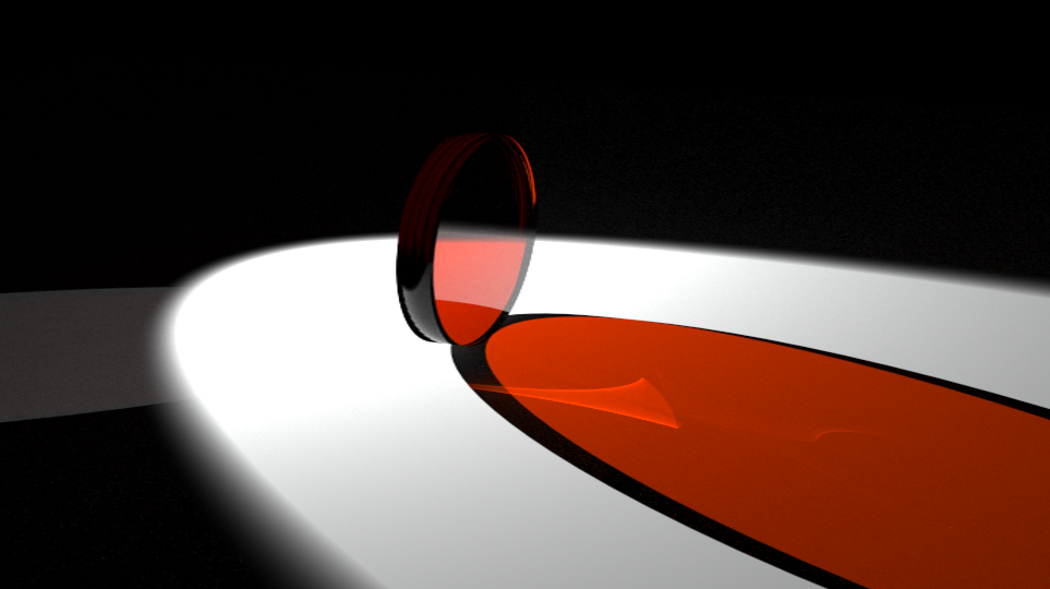
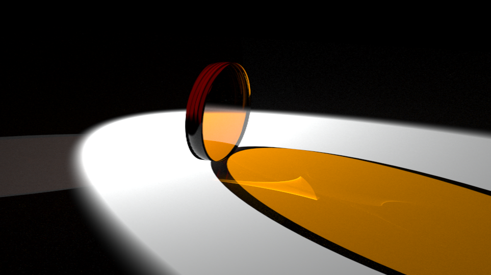
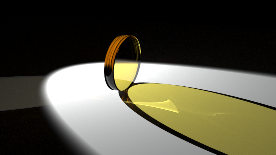
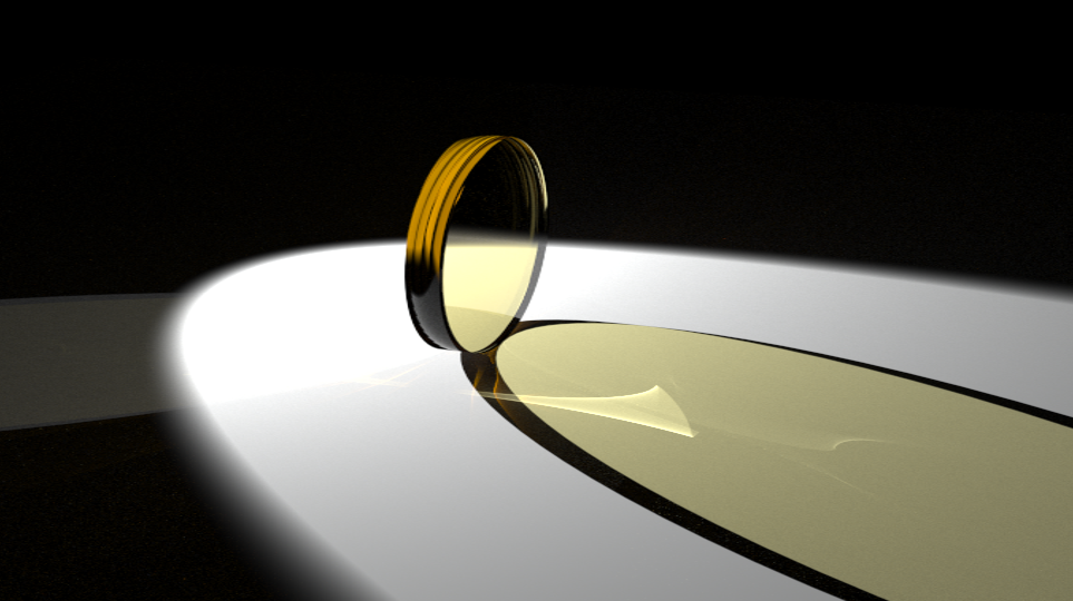
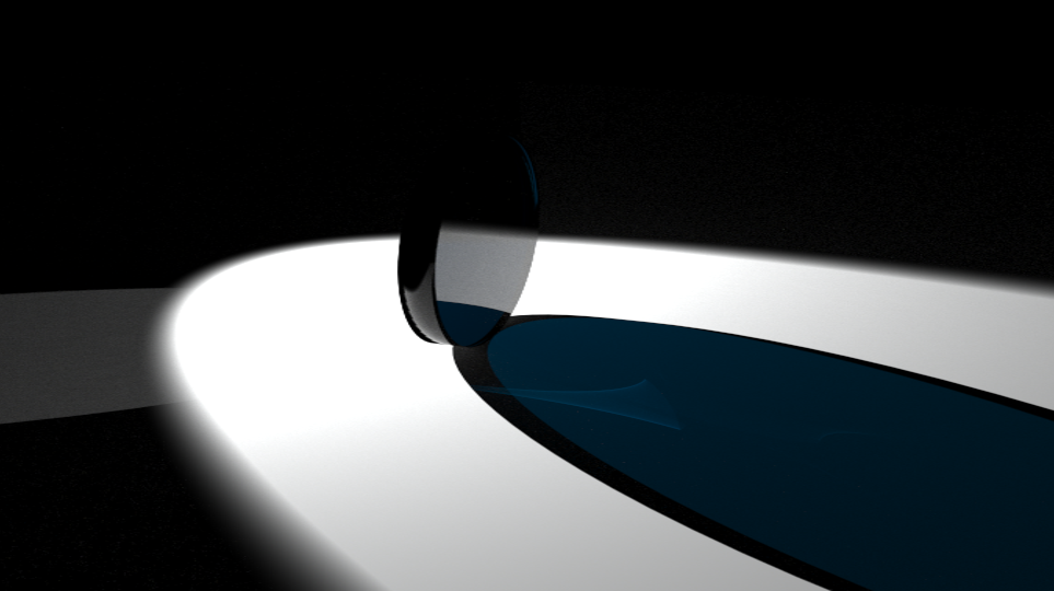
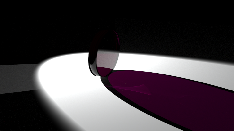
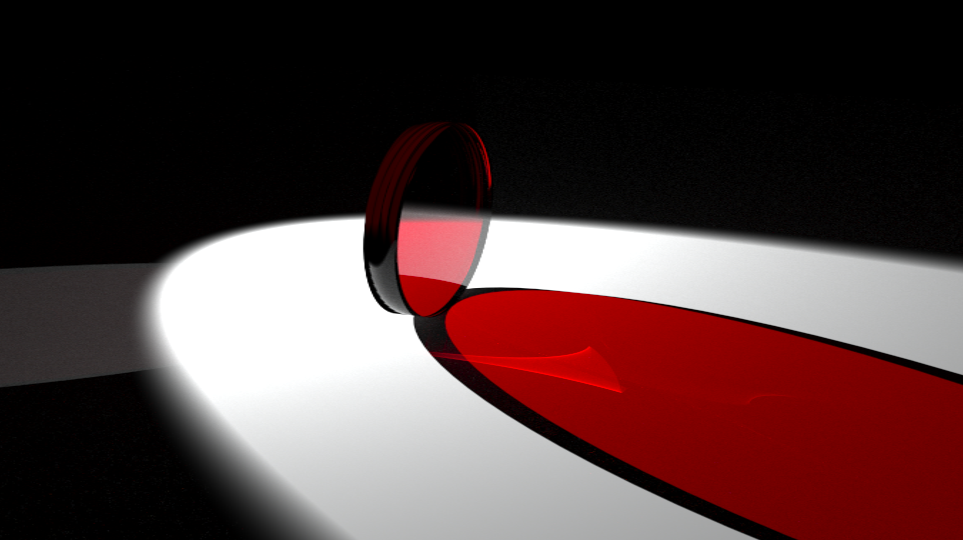
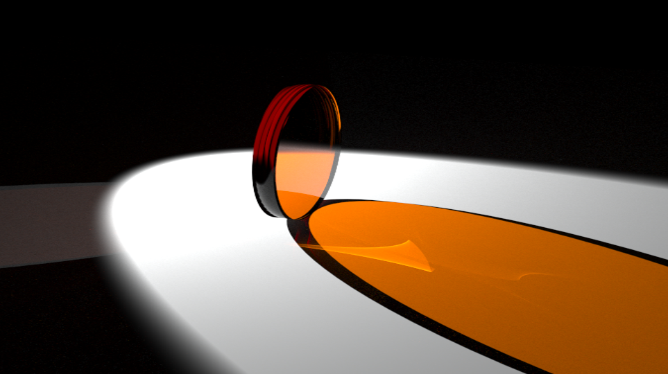
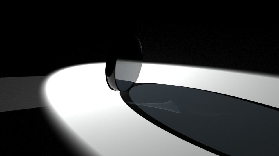
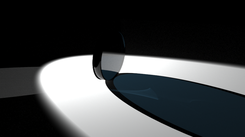
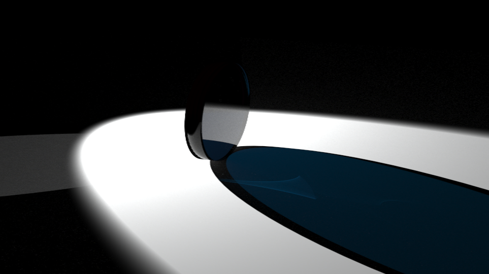
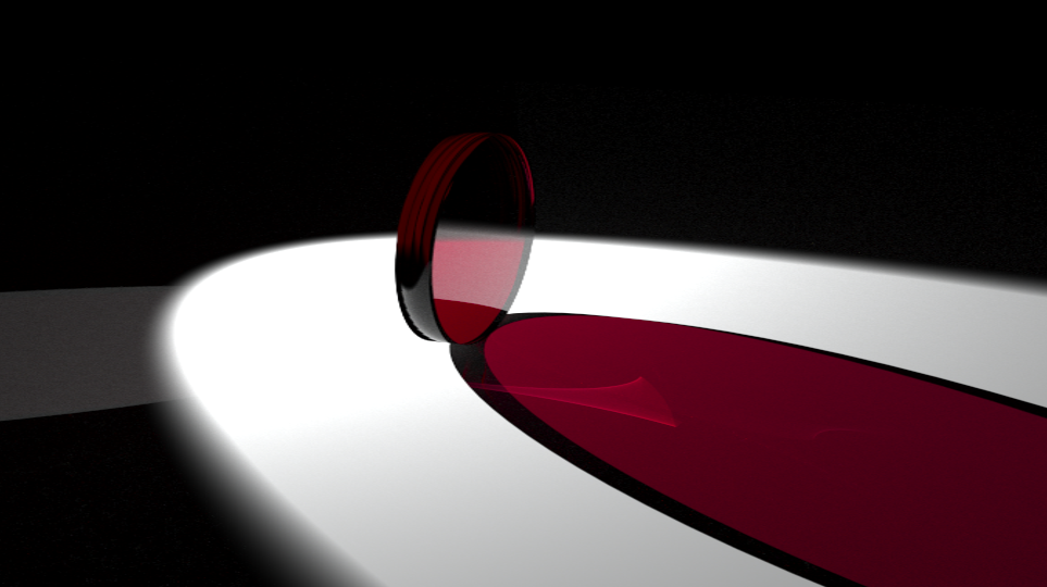
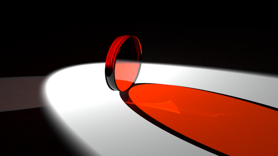
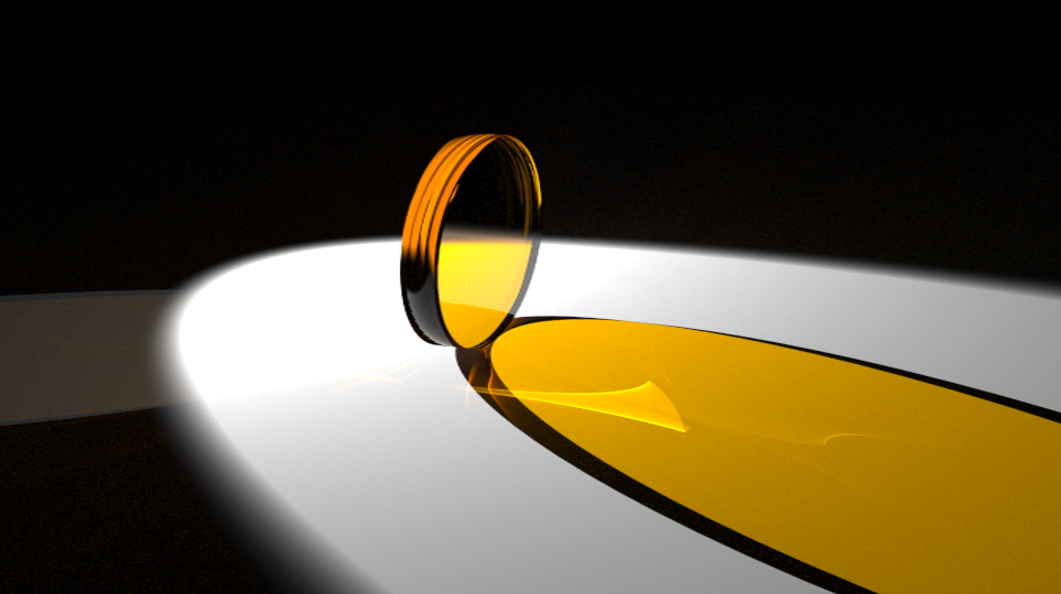
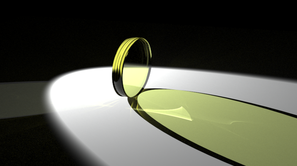
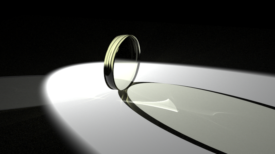
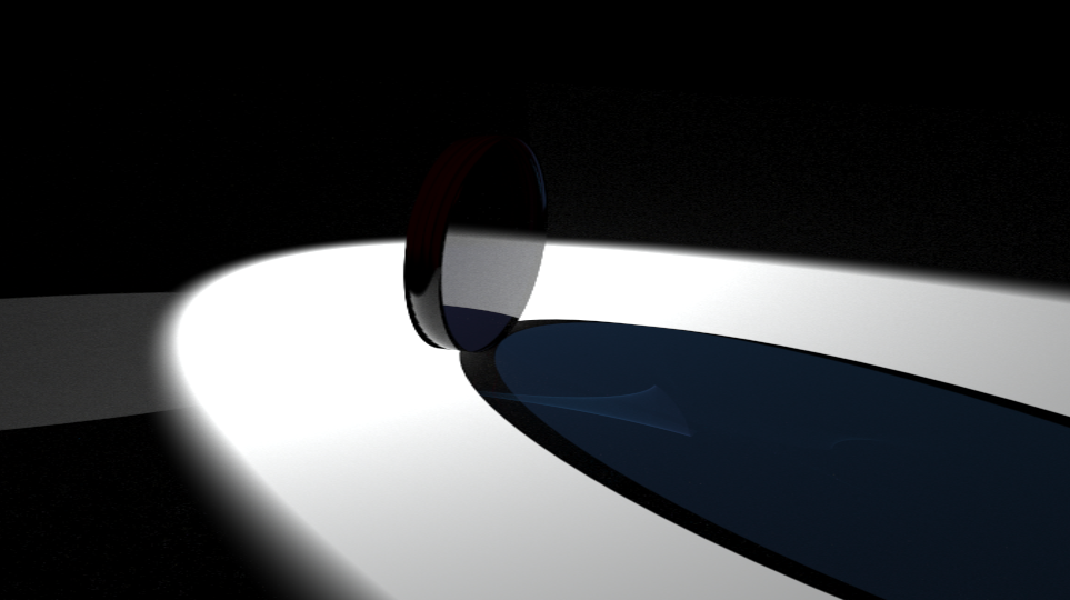
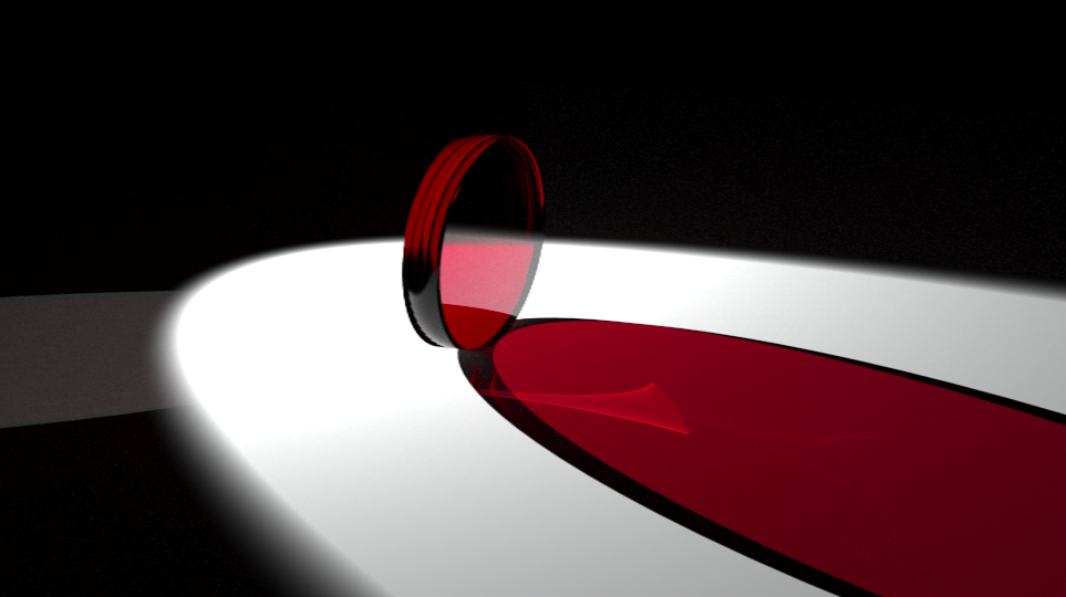
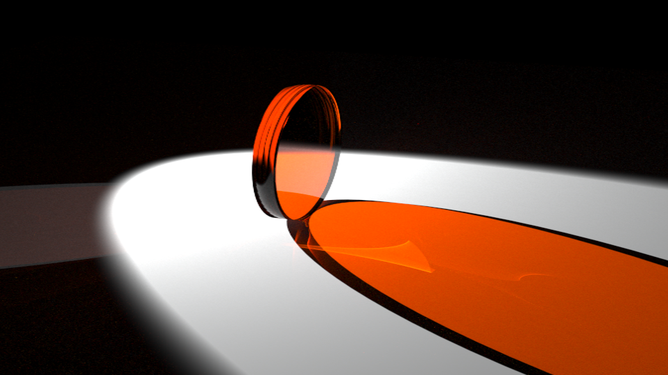
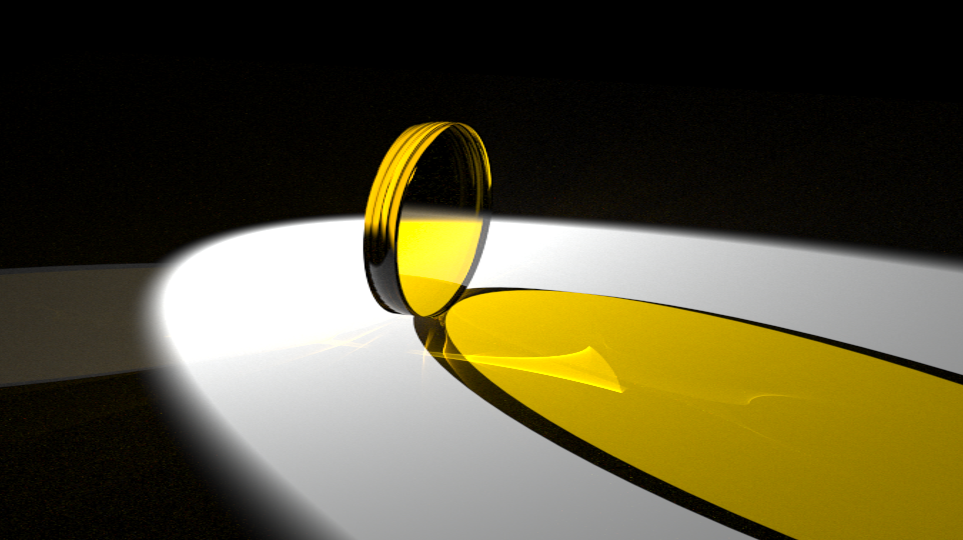
We varied the parameters in the equations to see how changing specific variables that contribute to the absorption spectrum data. The renderings from these runs proved to be successful, as a clear change in a material’s optical properties can be seen, and results from these tests will be shown below. We are working on expanding this and automate the entire process of scene creation, .dat file generation and rendering. The hope is to only require initial sweep range of a variable, and parameter values to be able to create a specific scene with a range of absorption inputs. The absorption spectrum range can then be seen and estimated through the renderings, as the only absoprtion spectrum range of interest is while the material’s optical properties' changes are observable. The below renderings are from a run where the height and peak position were fixed, but the broadening value was swept from 0 to 1.35 eV. The optical property change is evident at first, but begins to decrease as the broadening value increases.


Test Runs
We conducted several different runs, keeping all but one parameter constant in each test to see how a material’s optical properties would change based on a variable. Our major sweeps and the values used in each case are summarized below. The first run was a sweep of the broadening position, and the following four were sweeps of the peak position while varying the broadening and peak height values as clarified below. The changes in optical properties were only visible in a certain range of the varied parameters, so only the images that show the optical property change progression are included for each run. The values of the changing parameters are listed below their corresponding output image.
Run 1
Height : 20000002
Peak Position : 2.478
Swept broaden position from 0 to 80 in increments of 2

Broadening Values: 0 5
10
Broadening Values: 15 20
25

Broadening Values: 35 50
105
Run 2
Height : 10000002
Broadening value: 0.09
Swept peak position from 0 to 50 in increments of 2


Peak Position: 20 22
24
Peak Position: 26 28
32
Run 3
Height : 1000000.2
Broadening value: 0.09
Swept peak position from 0 to 50 in increments of 2

Peak Position: 14 18
20
Peak Position: 22 24
26
Peak Position: 28 30
32
Run 4
Height : 1000000.2
Broadening value: 0.009
Swept peak position from 0 to 50 in increments of 2
Peak Position: 12 16
18
Peak Position: 20 22
24

Peak Position: 26 28
30
Run 5
Height : 1000000.2
Broadening value: 0.0009
Swept peak position from 0 to 50 in increments of 2

Peak Position: 14 18
20
Peak Position: 22 24
28
Future Goals
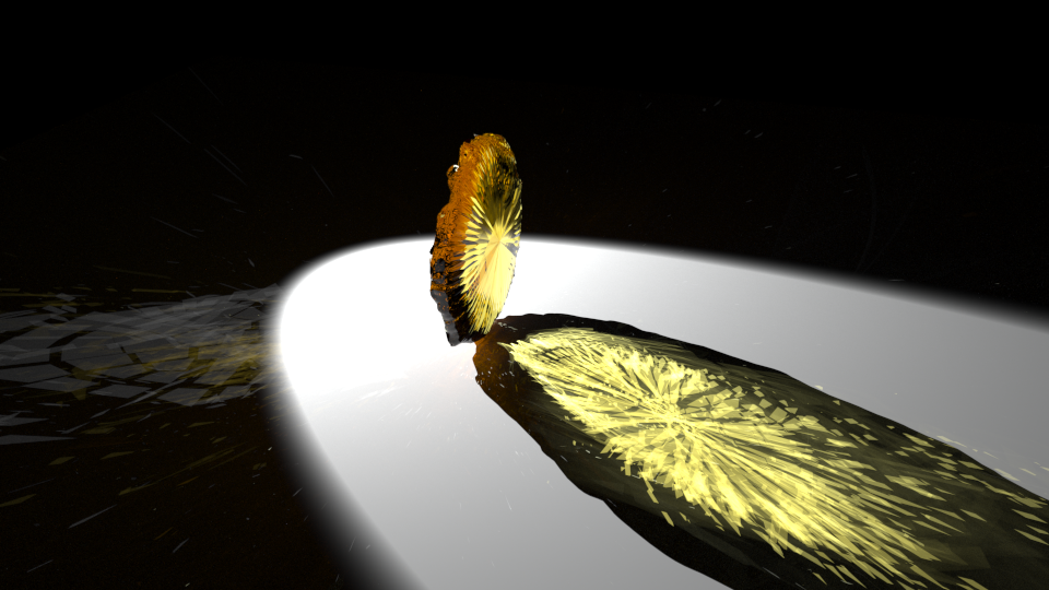
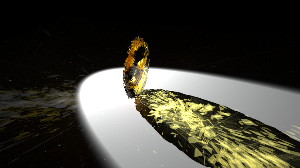
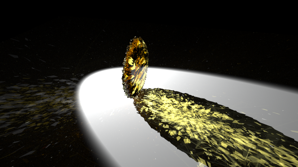
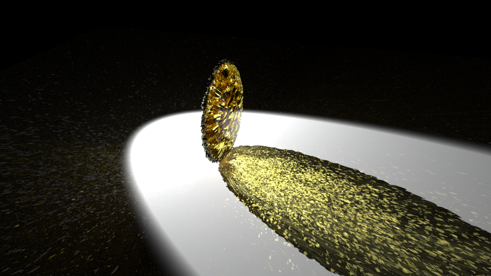
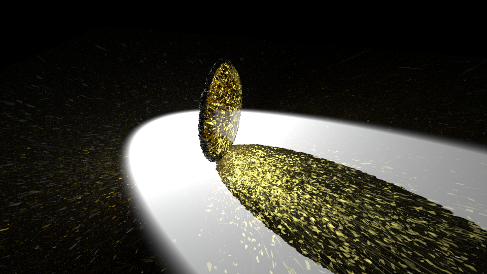
The most current run has been experimenting with the surface roughness of materials to see how this changes materials’ optical properties. We have been trying to find a consistent way of breaking up the geometries on the object’s surface in Blender. This has included creating smaller sub-surfaces, triangulating the face of lens and increasing the triangulation count. However, the challenges with this is the limitations that the computer’s memory places on how many geometries can be on the surface of a material. The creation and usage of more geometries requires more memory, and thus crashes the computer on which our tests have been running. The next step is to alter the subsurface and triangulation values in the Python scripts and to run the renderings on the high memory nodes on the Campus Cluster.
Our future goals for this project include creating a web interface that allows individuals to remotely use the program to work on materials design and to create renderings of materials with specific optical properties. We are continually working towards fully utilizing the capabilities of Blender, LuxRender and the Campus Cluster to be able to create accurate renderings of materials for potential use in computerized materials design work. Please feel free to contact me via e-mail : echen33@illinois.edu .
Software Used: